Microfluidics in industry
In this article of our series on microfluidic lab-on-chips, we describe how to apply and control the temperature in ‘miniaturised’ geometries, as is the case for microfluidic chips. Are you a designer or engineer who needs to realise strict temperature control – heating as well as cooling – within small dimensions? Here we tell you more about using thermo-electric modules.
PCR testing
There are many reasons why the sample fluid in a lab-on-a-chip must be brought to certain temperatures: to destroy contaminants, activate reagents, start or stop chemical reactions, etc. This is especially the case for PCR cycling (polymerase chain reaction), in which – simply said – a marked fraction of DNA or RNA is replicated multiple times, and the amount of ‘DNA of interest’ is doubled each cycle. A PCR cycle consists of three steps (denaturation, annealing, extension), each of which occurs at a specific temperature (resp. 95, 55 and 72 °C), to be applied with a tolerance of better than ±1° or even ±0.5°.
Nowadays, laboratory equipment is used in which a container holding tens to even hundreds of samples (each about 1 or a few ml in size; 1 ml = 1 cc = 1000 mm3), is thermally cycled. In addition to the time it takes to get the samples in the lab, prepare them and load them in the containers, also the limited temperature change rate and required hold time to assure correct temperature at each step throughout all samples, makes these tests take a long time to execute.
The PCR test using a microfluidic chip is aimed to be performed with a handheld or transportable device on site, i.e. at a point of care (PoC). Unlike lab equipment, this device analyses one sample at a time, but requires only a few tens (or less) of l total liquid volume (1 l = 1 mm3). The microfluidic approach makes it possible to achieve much higher temperature changes thanks to the high surface-to-volume ratio. The fluid very quickly takes on the temperature of the surrounding material, while advancing in the channel from one temperature zone to the next. This allows you to run a full cycling test in a few minutes.
Demonstrator setup
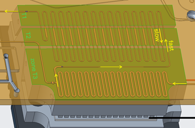
To cycle the fluid through the different zones, a meandering geometry can be used. If needed, one can prolong the residence time in a specific zone by adapting the meander, e.g. create ‘sub’-meanders or increase the channel section. The fluid channel, with a section of typically 50 to a few 100 m in width and height, is located on the surface of the plastic chip and is covered with a thin shielding membrane. This side of the chip is brought in close contact with the heating system. In our demonstrator setup this is a set of aluminium blocks (one for each temperature zone), which spread a quasi-homogenous temperature a few 0.1 mm deep into this side of the chip.
Other methods for thermal cycling are documented, e.g., where the liquid is spread over separate reservoirs and the full ‘chip’ is moved (rotated), such that each reservoir is transferred from one temperature zone to the next. Alternatively, the total liquid volume is pumped back and forth each cycle between the high and low temperature zones (right side of image above).
Thermo-electric modules
The correct heating (or cooling) of each block in the demonstrator setup is done with thermo-electric modules (TEMs). Other heating technologies are documented (e.g., in the chip integrated resistive or inductive heaters, microwave or IR-heating ...), however they can only heat (so, no cooling!), and complicate the chip design and fabrication (integrate also temperature measurement in the chip or even in the channels, add electric conductors and connectors ... e.g., using thin film technology).
TEMs are mostly used as coolers, then called TEC (thermo-electric cooler). They are based on the thermo-electric effect (Seebeck or Peltier effect): different temperatures (T) at two junctions of different conductive materials give rise to an electromotive force resulting in a voltage V, as occurs in thermocouples (Seebeck). The reverse definition states that, when applying a voltage over two junctions (hence a current running through them), it gives rise to a temperature difference and hence a heat flow between the junctions (Peltier). By reversing the voltage, the temperature difference reverses, and heat flow reverses as well. This explains also the naming ‘Peltier elements’.
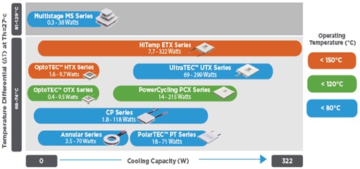
Using optimal engineered materials and geometries (sections and distances), as well as stacking hot and cold junctions in series (V ) and in parallel (I ), TEMs can be designed in any size. However, the rated power (typically a few hundredss of Watts cooling power, dependent on size) and maximum applicable temperature (typical 90 °C... up to 150 °C, dependent on internal technology and materials) of these elements is limited (example of product range from Laird Thermal Systems in picture below). If high temperatures and only heating is required, then simple resistive heaters are by far the best and cheapest option (e.g., printhead heaters in FDM printers).
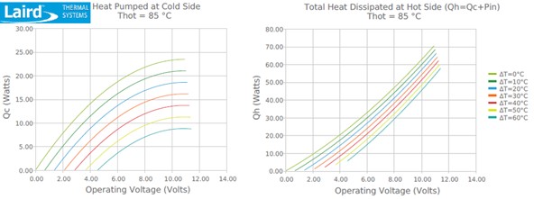
Electrically, a TEM can be considered as a simple resistor with slowly increasing resistivity with temperature. The heating power of such devices is much higher than the cooling power, as it incorporates also the internal resistive (Joule) heating (Pin=V*I). This is illustrated in the graphs below for a specific component.
For Thot=85 °C and T=30° (orange curves), applying a voltage of 8 V, the cooling power Qc pumped at the cold side reaches almost 15 W and heating power at the hot side Qh (=Qc+Pin) 38 W, from which Pin is almost 24 W, thus current is about 3 A and the resistance is about 2.66 . The cooling power reaches a maximum at around 10 V. Increased Joule heating at higher voltages will result in decreasing cooling performance.
Implementation in our demonstrator setup
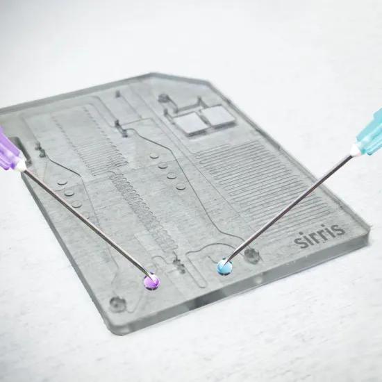
As illustrated in the first image (top of the article), one can see that the distance between the temperature zones is small (≈1 mm). From this, it is clear that one can expect heat to flow through the chip, but also through the insulation between the aluminium blocks, from the hotter to the cooler zones. This explains why, after a short transient where all heaters ‘heat’, the element at the low temperature zone will need to ‘cool’ (and for the element in the middle temperature zone it is not clear a priori whether it will heat or cool). The other side of the TEMs (away from the aluminium blocks) need to be ventilated via a heat sink to avoid too much cooling (and risk of condensation) during initial heating, and to avoid too much overall heating afterwards (from Pin).
In general, power supply is a constant DC voltage. To control the heating & cooling power, PWM control is mostly used. This can be realised with cheap components typically used for speed control of DC motors (forward/backward rotation realised by voltage reversing is equivalent to heating/cooling of TEMs).
Temperature control obviously also requires temperature measurements. These can be thermistors or thermocouples with a small footprint to be easily integrated in these small parts, without affecting the measurements, and which have a fast response. In preassembled coolers (TECs) typically NTC thermistors are used. However, for heating above 70 °C, their resistance decreases that much that self-heating from higher current cannot be avoided. Therefore, small K-type thermocouples are a better option. The accuracy in the range 50-100 °C (or even 0-100 °C) is very good, despite the relatively lower specified accuracy over the whole possible measuring range. After calibrating different units (K-type thermocouple + MCP9600 chip, but other chips could be used as well), just a constant offset of ~0.7° needed to be introduced over the temperature range of interest to reach an accuracy (and repeatability) of ±0.25 °C.
Project funding
VLAIO COOCK Medical diagnostics goes micro and smart, HBC.2021.0560
More information about the project
Medical diagnostics goes micro and smart
Would you like to know more?Most of the production techniques described in this article are available from Sirris for creating your pre-industrial microfluidic prototypes. Contact us for more information
|
