Machine tool performance - Part 2
Errors in machined parts are closely associated with errors in the machine tool, and usually they are identified as deviations of the actual cutting point from the nominal or commanded position or trajectory in the workspace. For the evaluation and measurement of machine tool accuracy, it is deemed important to determine and understand the major sources of error in a machine tool.
The main error sources can be divided into five categories:
- Geometric and kinematic errors
- Thermal errors
- Static load effects
- Dynamic errors
- Motion control and servo errors
Let's take a closer look to have a better understanding:
Geometric and kinematic errors
Geometric errors are associated with the design of the machine tool components, such as guideways, machine table, bearings, lead screws etc. These are manufacturing imperfections leading to deviations in the relative position and the orientation of the tool with respect to the workpiece.
Kinematic errors are related to the trajectory of the moving components of a machine tool, like the linear or rotating axes. Misalignments during assembly of these moving components can lead to kinematic errors, such as squareness and parallelism between the axes. These errors are significant during simultaneous movement of multiple axes while linear or circular interpolation motion.
Thermal errors
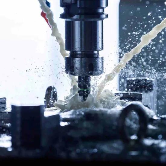
These errors arise due to thermal expansion of the different components of the machine tool structure leading to geometric and dimensional changes. There are several heat sources within a machine tool, like servo drives, spindles, pumps and friction in bearings, that leads to thermal distortion of its components. Furthermore, the cutting process itself generates a significant amount of heat though the chips and the cutting fluids, which adds to the thermal stresses. The ambient air temperature also influences the thermal gradients and stresses to the machine structure leading to errors.
Static load errors
These errors are caused by static and quasi-static loads and forces, due to the own weight of the machine components, the workpiece mass, fixtures, and the cutting process, leading to deformations of the machine structure. The effect of such static loads can be identified by measuring the geometric errors of the machine tool.
Dynamic load errors
The structural stiffness loop of a machine tool is usually subject to dynamic effects that influence its dynamic behaviour, producing distortions in the tool path trajectory to be realised. These dynamic loads could be due to varying cutting forces, due to tool wear, inertial forces due to acceleration and deceleration of the machine axes, self-excited vibrations or chatter etc. These dynamic loads alter the dynamic stiffness of the system, leading to dynamic load errors.
Motion control errors
Machines axes movements are achieved by accurate servo control drives. These drives should be responsive to the programmed axis positions, feeds and speeds and other movements needed during machining. These servo drive movements can introduce errors while interpreting NC commands.
In the next article we will look into the methods to estimate and measure these errors.
Would you like to learn more about this topic and find tools to implement in your shop floor? You can attend our forthcoming workshop on stainless-steel machining, on 16 November 2023, where you can learn hands-on about practical tools based on physical models developed to help you choose optimum conditions for your machining processes. You can find more information about the workshop and register in the following link: Stainless-steel machining | Sirris.
For any further questions, please do not hesitate to contact us.


